News
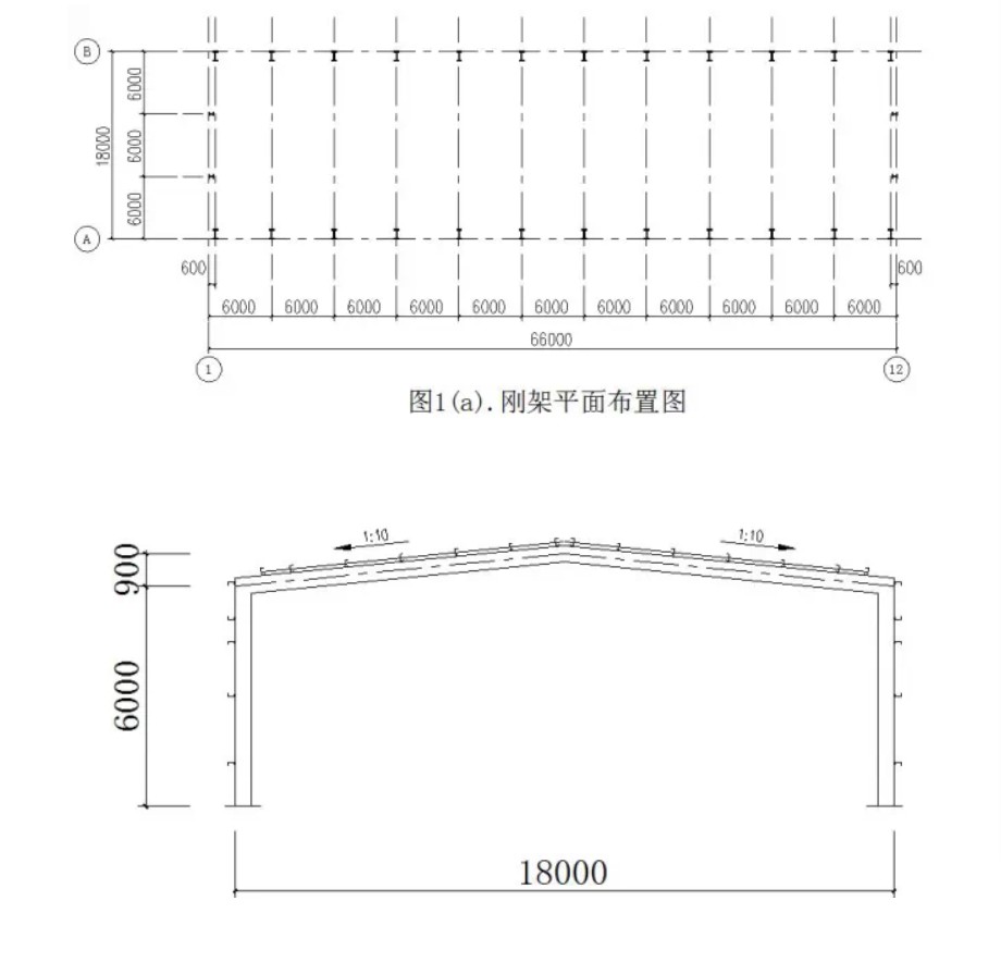
A factory building of a processing factory in Henan Province. The factory building is a single-story building with a single-span double-slope portal frame with a frame span of 18m and a column height of 6m; there are 12 rigid frames with a column spacing of 6m and a roof slope of 1:10; earthquake The fortification degree is 6 degrees, the design seismic group is the first group, and the design basic seismic acceleration value is 0.05g. The plane layout of the rigid frame is shown in Figure 1(a), and the form and geometric dimensions of the rigid frame are shown in Figure 1(b). The roof and wall panels are all polyurethane composite insulation boards; considering economy, manufacturing and installation convenience, the purlins and wall beams are made of cold-formed thin-walled C-shaped steel with a spacing of 1.5m, the steel is made of Q235 steel, and the welding rod is of E43 type。
Load calculation
(1) Calculation of load value
1. Standard value of permanent roof load (for horizontal projection surface)
YX51-380-760 color profiled steel plate 0.15 KN/m2
50mm thick thermal insulation glass wool board 0.05 KN/m2
PVC aluminum foil and stainless steel wire mesh 0.02 KN/m2
Purlin and support 0.10 KN/m2
Rigid frame inclined beam dead weight 0.15 KN/m2
Suspension equipment 0.20 KN/m2
Total 0.67 KN/m2
2. Standard value of roof variable load
Roof live load: Considering that the roof is not on the roof, 0.50 KN/m2.
Snow load: basic snow pressure S0=0.45 KN/m2. For single-span double-slope roof, roof slope angle
α=5°42'38″, μr=1.0, and the standard value of snow load Sk=μrS0=0.45 KN/m2.
The larger of roof live load and snow load is 0.50 KN/m2, and the ash load is not considered.
3. Self-weight standard value of light wall and column (including column, wall frame, etc.) 0.50 KN/m2
4. Wind load standard value
Calculated in accordance with the provisions of Appendix A of "Technical Regulations for Steel Structures of Portal Rigid Frame Light Buildings" CECS102: 2002.
The basic wind pressure ω0=1.05×0.45 KN/m2, the ground roughness category is Class B; the wind load height variation coefficient is adopted according to the "Building Structure Load Code" (GB50009-2001), when the height is less than 10m, the height is 10m The value at is adopted, μz=1.0. Wind load carrier type coefficient μs: windward side column and roof are respectively +0.25 and -1.0, leeward side column and roof are respectively +0.55 and -0.65 (CECS102: 2002 middle area).
5. earthquake effect
According to Recommendation 18.8.1 in "National Civil Construction Engineering Design Technical Measures-Structure": The steel structure of single-story portal rigid frame light-weight house generally does not require seismic calculation in areas where the seismic fortification intensity is less than or equal to 7 degrees. Therefore, the structural design of this project does not consider earthquake effects.
Calculation of the standard value of the load acting on each part
Roofing:
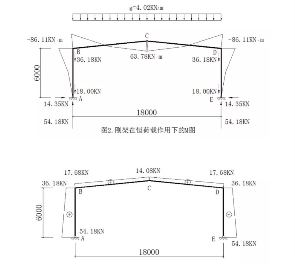
Standard value of dead load: 0.67×6=4.02KN/m
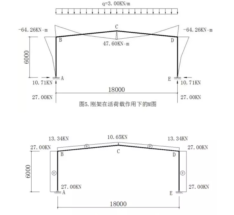
Standard value of live load: 0.50×6=3.00KN/m
Column load:
Standard value of dead load: 0.5×6×6+4.02×9=54.18KN
Standard value of live load: 3.00×9=27.00KN
Standard value of wind load:
Windward side: on the column qw1=0.47×6×0.25=0.71KN/m
On the beam qw2=-0.47×6×1.0=-2.82KN/m
Leeward side: qw3 on the column=-0.47×6×0.55=-1.55KN/m
On the beam qw4=-0.47×6×0.65=-1.83KN/m
Internal force analysis
Considering the small span of the rigid frame of this project, the low height of the workshop, the load conditions and the convenience of rigid frame processing and manufacturing, the rigid frame adopts a uniform cross section, and the beam and column use the same cross section. The column feet are designed with hinged support. The elastic analysis method is used to determine the internal force of the rigid frame. Quoting "Steel Structure Design and Calculation" (edited by Baotou Iron and Steel Design and Research Institute, Machinery Industry Press) in Table 2-29 (calculation formula for hinged column-foot portal frame) to calculate the internal force of the frame.
1. Under dead load
λ=l/h=18/6=3
ψ=f/h=0.9/6=0.15
k=h/s=6/9.0449=0.6634
μ=3+k+ψ(3+ψ)=3+0.6634+0.15×(3+0.15)=4.1359
HA=HE=qlλΦ/8=4.02×18×3×0.5289/8=14.35KN
MC=ql2[1-(1+ψ) Φ]/8=4.02x182[1-(1+0.15)×0.5289]=63.78KN·m
MB=MD=-ql2Φ/8=-4.02×182×0.5289/8=-86.11KN·m
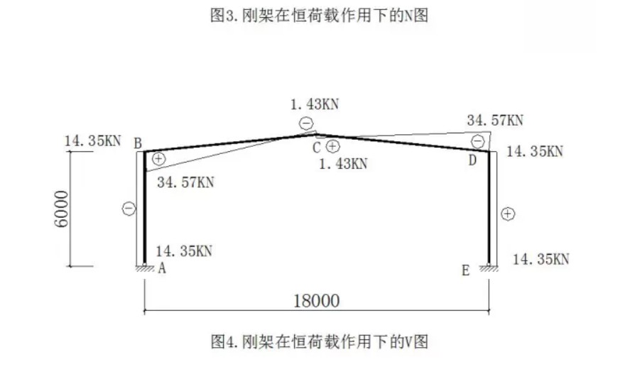
The internal force of a rigid frame under a dead load is shown in the figure.
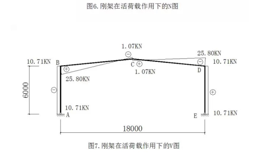
The "+, -" signs of internal force calculation stipulate: the bending moment diagram is based on the outside tension of the rigid frame as positive, and the bending moment diagram is drawn on the tension side; the axial force is based on the compression of the rod as positive, and the shear force is around the rod end. Clockwise rotation is positive.
1. Under live load
VA=VE=27.00KN
HA=HE=3.00×18×3×0.5289/8=10.71KN
MC=3.00×182[1-(1+0.15)×0.5289]/8=47.60KN·m
MB=MD=-3.00×182×0.5289/8=-64.26KN·m
The internal force of the rigid frame under live load is shown in the figure
3. Under wind load
The wind load acting on the roof can be decomposed into the horizontal component qx and the vertical component qy. Now calculate separately, and then superimpose.
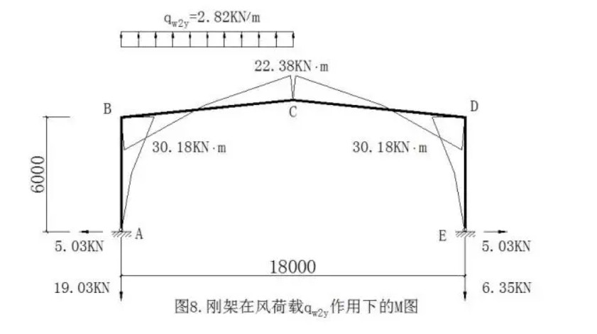
(1) Under the action of the vertical component qw2y of the wind load on the windward side beam
VA=2.82×9-6.35=19.03KN
HA=HE=qlλΦ/4=2.82×18×3×0.1322/4=5.03KN
MB=MD=5.03×6=30.18KN·m
MC= ql2[α2-(1+ψ) Φ]/4=2.82×182×[0.52-1.15×0.1322]/4=22.38KN·m
The internal force of the rigid frame under the action of qw2y is shown in the figure
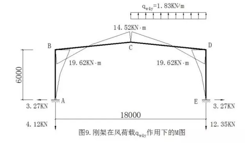
(1) Under the action of the vertical component qw4y of the wind load on the leeward side beam
VA=1.83×9-4.12=12.35KN
HA=HE=qlλΦ/4=1.83×18×3×0.1322/4=3.27KN
MB=MD=3.27×6=19.62KN·m
MC= ql2[α2-(1+ψ) Φ]/4=1.83×182×[0.52-1.15×0.1322]/4=14.52KN·m
The internal force of the rigid frame under the action of qw4y is shown in the figure
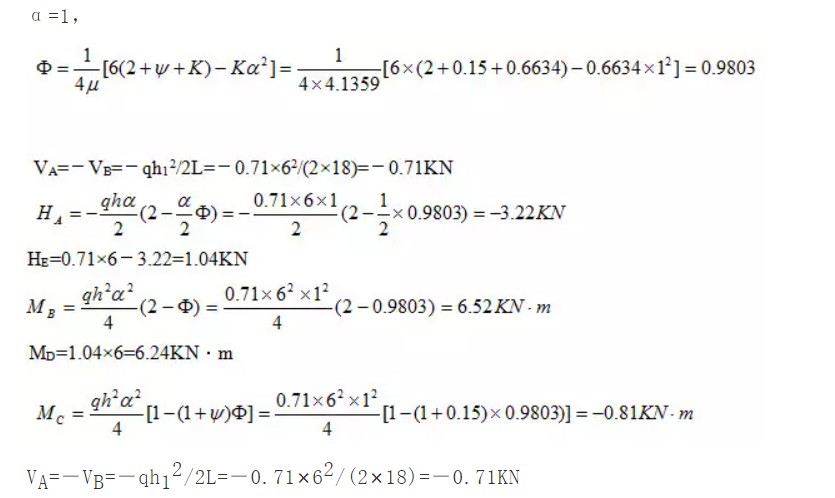
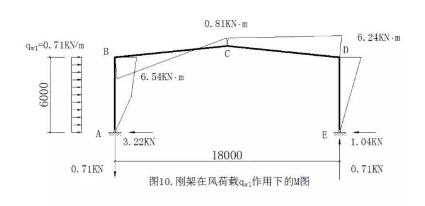
(1) Under the action of the wind load qw1 on the column on the windward side
The internal force of the rigid frame under the action of qw1 is shown in the figure
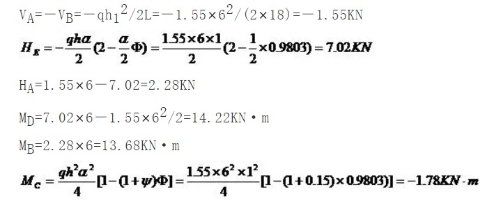
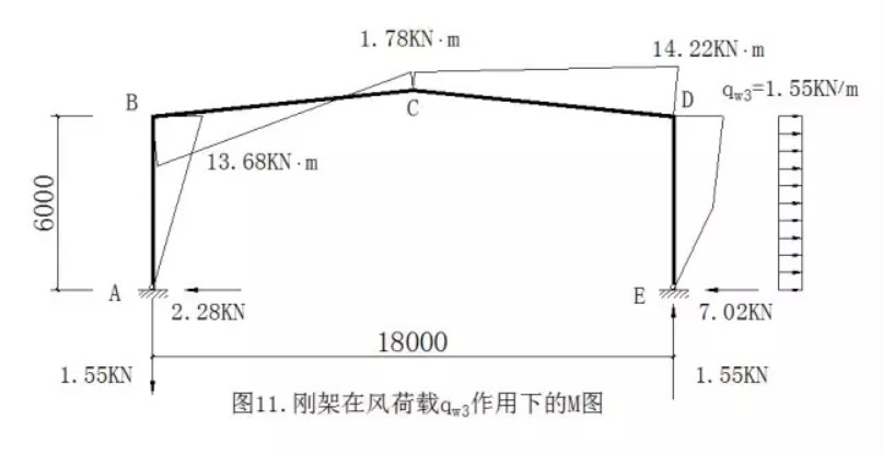
(4) Under the action of the wind load qw3 on the leeward side column
The internal force of the rigid frame under the action of qw3 is shown in the figure
(4) Under the action of the wind load qw3 on the leeward side column
The internal force of the rigid frame under the action of qw3 is shown in the figure.
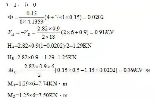
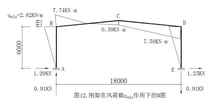
(5) Under the action of the horizontal component qw2x of the wind load on the windward side beam
The internal force of the rigid frame under the action of qw2x is shown in the figure.
Get in contact to KXD Steel

